
In the first episode, let’s talk about drawing a single triangle on your screen. By analyzing a frame captured from a triangle application, let’s learn what need to offer to the operating system to render this blue triangleIn our inaugural episode, we’ll explore how to render a single triangle on your screen. By examining a frame captured from a simple triangle-rendering application, we’ll learn about the essentials provided to the operating system to achieve this.
Begin by downloading “S1-HelloTriangle.zip” from the shared drive and extract its contents. Open the frame using the “Frame Analyzer” to proceed.

You’ll notice the blue triangle in the center—the outcome of our rendering. On the left, the API log lists just one item, signifying that a single “DrawInstanced” API call was responsible for rendering our triangle on the screen.
By selecting this draw call, a new “Resource” window appears, showcasing three categories: Input(In), Execution(Exe), and Output(Out). These resources are crucial for understanding the data required for rendering.

We will through those resources one by one to find out what has been used in this rendering.
Starting with the Input section, we find two items. ‘B:’ denotes a buffer, followed by a unique SHA code. The term ‘VBV’ (Vertex Buffer Views) indicates that this buffer stores the vertices.
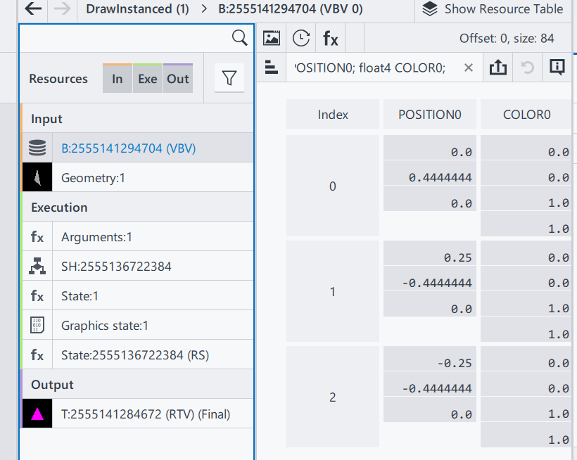
This particular buffer contains a trio of vectors, each comprising two components: Position and Color.
Position: A trio of float vectors, each within the range of [-1.0, 1.0], designating the x, y, and z coordinates. For our 2D example, all z-values are zero, with the x/y pairs forming a triangle onscreen.
Color: A quartet of float vectors, ranging from [0.0, 1.0], representing the ‘RGBA’ color values where, in our case, we have full blue with complete opacity.
Why do colors define in floating points? While designing the interface, ideally an application doesn’t need to know what hardware it needs to be executed. Thus, when rendered in an 8-bit rendering system, the result color will be in range [0, 255]; on a 10-bit rendering system (Also named HDR10), it means the final range will be in [0, 1023].
Why colors and transparencies are defined on the vertices instead of the surface/triangle? In a modern rendering system, a surface is always represented by 3 vertices, and in general the number of surfaces will be larger than the number of vertices. In this case, defining color and transparency information on vertices can reduce the amount of parameter savings. The color and transparency values of a vertex are reused for all surfaces that share that vertex.
Geometry Input: A visual result of the input vertices, drawing a triangle in a 3D space.
That’s the end of Input section.
In execution section, to simplify this episode, we are only focusing on Arguments and Shader(SH):
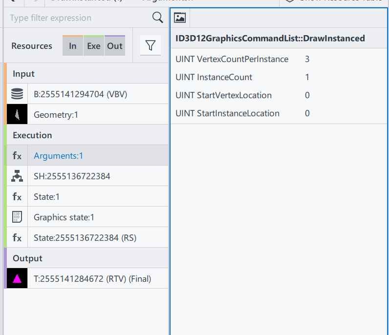
ID3D12GraphicsCommandList::DrawInstanced: This is the draw command used in this rendering process. Definitions can be found here. ID3D12GraphicsCommandList::DrawInstanced
VertexCountPerInstance: Number of indices read from the index buffer for each instance.
InstanceCount: How many instances/surfaces are there in this draw call. Here we only have 1 triangles.
StartVertexLocation: Sometimes the vertex buffer saves additional information for other draw calls. Here offer an offset to find the correct vertex
StartInstanceLocation: A value added to each index before reading per-instance data from a vertex buffer.
From the DrawInstanced command’s arguments, we ascertain the intention to draw a single instance represented by three vertices.

Shader codes of this rendering system, as a programmable input to define how to render a result.
SH: 2555136722384 Shader resource, with its HASH
HLSL(High-Level Shader Language): A shader language developed by Microsoft
VSMain: The main function of Vertex Shader
PSMain: The main function of Pixel Shader. This will be the final value of a Pixel
The full design and execution of the shader system is complicated, and will be gradually extended in this series, when the demo is getting more complex. To check the full DX12 pipeline system Pipelines and Shaders with DX12.
And that wraps up the Execution section! We’ll touch upon the Output results when relevant in future discussions.
To recap, we’ve covered:
- Input: Vertex positions and color data.
- Shader: Source code specifying VSMain and PSMain functions.
With these inputs prepared, we’re set to execute the “DrawInstanced” command:
DrawIndexedInstanced(3, 1, 0, 0, 0)
Executing this function draws the blue triangle on the screen, achieving our rendering goal.
Thank you for joining Episode 1! Your thoughts and questions are welcome in the comments below. Stay tuned for the next installment!

Leave a comment